The place to be when you have TEA. Discuss all kinds of test equipment.
Important: Use tags for the type of equipment your topic is about.
Forum rules
Use tags for the type of equipment your topic is about. Include the "repairs" tag, too, when appropriate. If a new tag is needed, request one in the TEAdministration forum.
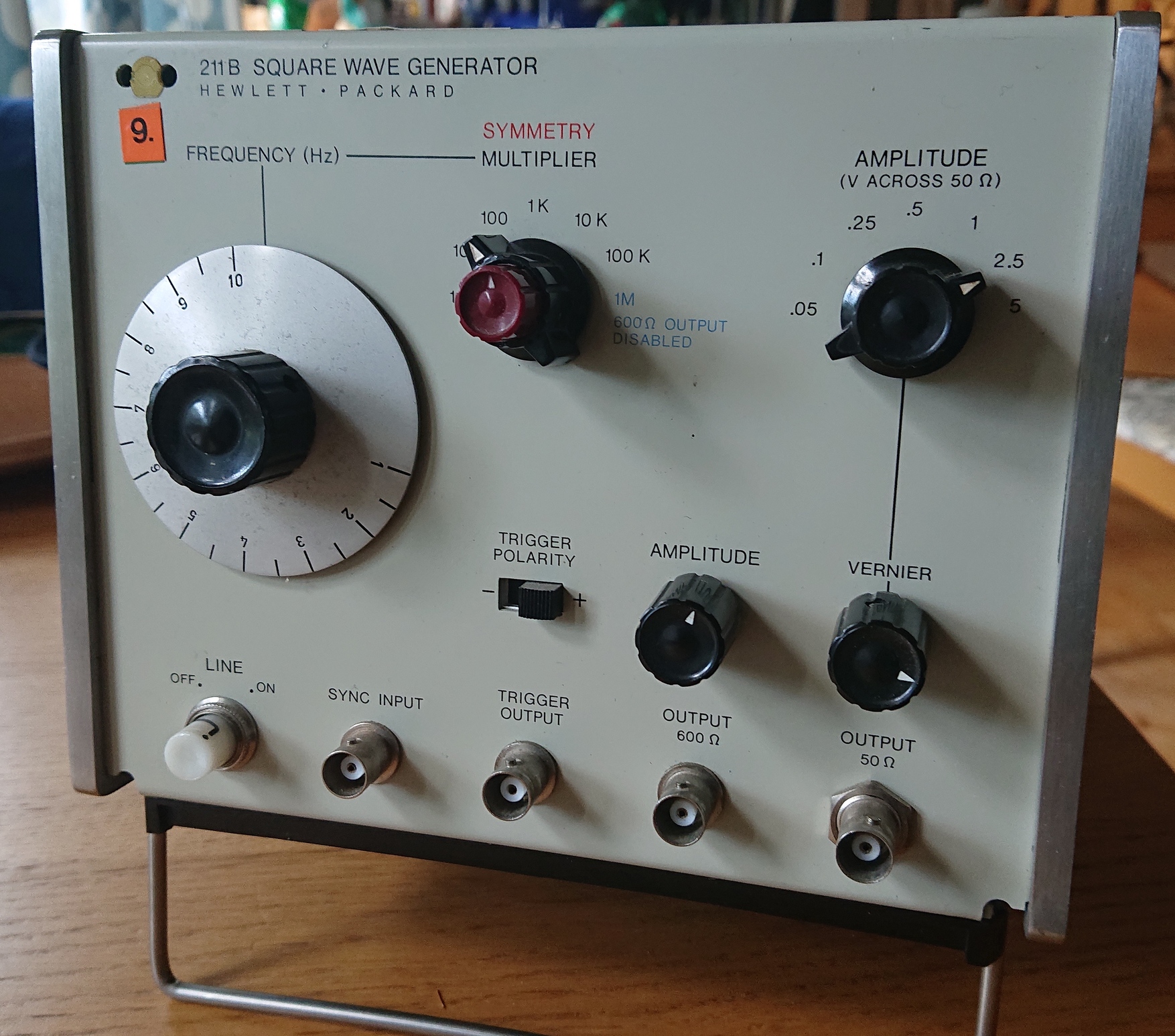
Next project. hp 211A Square Wave Generator. From Facebook Marketplace. Extremely dirty on the outside and the cabinet will need re-painting. Papa Smurf's paint shop will be opened and will spray it gray.
Inside is not too bad and is complete. There are lots of crapacitors that will have to be changed including at least 4 black beauties.
An old gray beard with an attitude. I don't bite.....sometimes
The front panel cleaned up well. I used automotive polishing compound on the aluminum frequency dial and it got rid of 90% of the surface corrosion. The corroded BNC connectors will be replaced.
Next up is cleaning the case in prep for paint. The actual painting may have to wait since it's done outside and the weather is still chilly.
There will be no attempt at power up until after the PSU caps are replaced.
An old gray beard with an attitude. I don't bite.....sometimes
Some time back I also snagged their later, much simpler sand filled cousins - the 220A and 221A. The 220A outputs a negative square wave, the 221A a positive one. Both are badly in need of cleaning and restoration, as one needs a bit of imagination to consider their outputs to be square waves. Interestingly, both are early examples of their respective engineering revs, the first being the 92nd off the line (815-00192) and the second the 98th (927-00198). As I recall, I had that search going on the Bay of Malcontent for quite a long time; I don't think they sold particularly well (or perhaps were considered disposable; list price for either in 1969 was $195 while the 211A was $400 and the 211B was $450).
MED6753 wrote: ↑Mon Mar 03, 2025 10:46 pm
Next project. hp 211A Square Wave Generator. From Facebook Marketplace. Extremely dirty on the outside and the cabinet will need re-painting. Papa Smurf's paint shop will be opened and will spray it gray.
Inside is not too bad and is complete. There are lots of crapacitors that will have to be changed including at least 4 black beauties.
This looks like a neat project. From the pictures it looks like it's a mix of original and replacement tubes in there. Also, is the one 0.1 MFD capacitor visible under the chassis an American Radionics Ceracap? The package kind of looks like one of those.
Repairs to the front panel. Replaced corroded BNC's. The binding post for the 600 Ohm output was cracked. Super glue fixed that. The plastic cursor to set accurate frequency was broken and missing. Made one with black paint.
The mechanical restoration is now complete. Next is the electrical restoration. Still have to prepare the list and order the parts from Mouser. Stay tuned.
An old gray beard with an attitude. I don't bite.....sometimes
I'm finding differences in the manual I downloaded from the hp archives and this unit. V12 is shown on the schematic as a rather uncommon 5V3 Rectifier. My unit has V12 as a much more common 5U4GB Rectifier. I haven't found any other differences yet.
Started the re-cap. C26 and C27 changed out. The old C27 can is disconnected and will remain in place. hp likes to rivet the cans to the chassis so I'm not going to bother to drill out the rivets. Been down that road before with other hp units where it was necessary to install replacements.
An old gray beard with an attitude. I don't bite.....sometimes
5V3A has an entry in the 1966 RCA Receiving Tube Manual. 5V3 is mentioned in the obsolete section. I've never come across it before. 5U4 isn't much less capable. On the face of it, either looks like overkill in this application.
I'd guess it went out of production, or became expensive, into the manufacturing run of this oscillator. 5V3 and 5U4 look to be plug in replacements for each other, as were many of those rectifiers.
My 1970 edition of the RCA Receiving Tube Manual is buried somewhere downstairs in the storage unit but I did compare specs of the 5V3 vs the 5U4 online and they are pretty much equivalent. I've never seen a 5V3 in the wild either.
An old gray beard with an attitude. I don't bite.....sometimes
More work. C25 replaced. Had to install a terminal strip to accommodate the replacement cap.
Since that was the last capacitor to be replaced in the PSU decided to do a test power up. First try resulted in nothing. Completely dead. A bad power switch is the culprit. Don't have a replacement so I did a temporary jumper. Got power and after a few minutes of settling was able to adjust the PSU to spec -195V.
Do we have an output? Yes, but it looks more like a pulse than a square wave. There's a symmetry adjustment it won't adjust to 50/50. The balance of the re-cap will be done first and if this is still an issue we'll find the cause.
An old gray beard with an attitude. I don't bite.....sometimes
I had to replace the line cord. The insulation on all the conductors was so brittle that any flexing of the cables would cause it to crack and fall off. I tried stripping back the cord to see if any good insulation was present and no go. This line cord is a freaking fire hazard. Not any more. Fixed. Also replaced the defective power switch.
Next up. Those 2 large white 2uf tubular capacitors.
Replacements are those brown units mounted on terminal strips.
An old gray beard with an attitude. I don't bite.....sometimes
At one time they were a mainstay of the electronics industry. Last time I looked there was a very limited selection and they were dear. I've snapped them up when I've seen them going cheap. No doubt they are still available, at a price, for the vintage hifi crowd. You have to get inventive when fitting new parts to this old gear.
Fixed line cords are a damned nuisance, even if they haven't degraded to the point where they are dangerous. IEC connectors were a brilliant invention.
I've got a load of those turret tag boards and odd tag strips and tag boards, and also some 28 pin DIL fibre glass boards - could be useful for dealing with a 28 pin DIL package with damaged pins. I've scooped them up whenever I've seen them going cheap at swapmeets.
I was looking over things today and noticed something. R29 does not look very healthy. Burnt I'd say. It's a 1.5K, 1W, 1%. I don't see any obvious reason why it would burn unless V5 is drawing excessive cathode current. When I get a chance I'll replace R29 and see what happens. It just so happens that this is the area that controls the symmetry of the square wave.
An old gray beard with an attitude. I don't bite.....sometimes
MED6753 wrote: ↑Tue Apr 22, 2025 10:43 pm
I was looking over things today and noticed something. R29 does not look very healthy. Burnt I'd say. It's a 1.5K, 1W, 1%. I don't see any obvious reason why it would burn unless V5 is drawing excessive cathode current. When I get a chance I'll replace R29 and see what happens. It just so happens that this is the area that controls the symmetry of the square wave.
Common positive tube circuits always mess with me. Looking at the voltages given in the diagram, it looks like that 1.5K R29 should only have 20 volts across it and dissipate 0.267 W under normal operation which wouldn't be nearly enough to cook a 1W resistor like that. It'll be interesting to see if the 175 volt point settles in on spec or close to it once you replace R29 or if there's something else faulty that's messing with the square wave symmetry and also pulling the voltage there down and causing R29 to dissipate excessive power. Out of curiosity, are you going to measure the resistor once it's out of there and how badly the overheating shifted its value?