EC8010 wrote: ↑Thu Nov 20, 2025 7:52 pm
Admittedly, those old Tek oscilloscopes with distributed amplifiers have rather a lot of valves, but the days of buying a Tek 545 with power supply on lab trolley for £20 are long gone.
Zenith and I went to the Telford hamfest, where they couldn't give Tek7000 series plus plugins away. Back in the day I never liked them anyway; I preferred 465s

(I bought one for work many years ago because we needed the trolley.) The Panaplex display on my Solartron 7075 DMM is lovely to behold, but the meter behind it is nothing like as good as my (much newer) Hioki DM7275.
Yeah, but you can
tweak adjust 7075s, to you heart's content. No comments on the wisdom of that, please!
That 500MHz PCB is wonderful,with C64 the trimmer capacitor between L70 the centre-tapped inductor. And as for L69's coupling critically adjusted by bending it towards L70... Magic! Are those nuvistors? I'd have loved to shown something like that to the students when I was teaching. Looking at audio prices, there seem to be a lot of people around with more money than sense. Over the last twenty years, I've dithered and havered for six months over a piece of audio gear yet spent the same amount of money (and more) on test gear with nary a qualm.
You are actually looking at C70; C64 is hidden on the other side of the double-sided PCB. L70 is the horseshoe "half transformer" between the two nuvistor anodes. (Nuvistors are still available NIB on fleabay for ~£7, IIRC) L69 is indeed the piece of bendable wire; move it closer to L70 if the output isn't strong enough

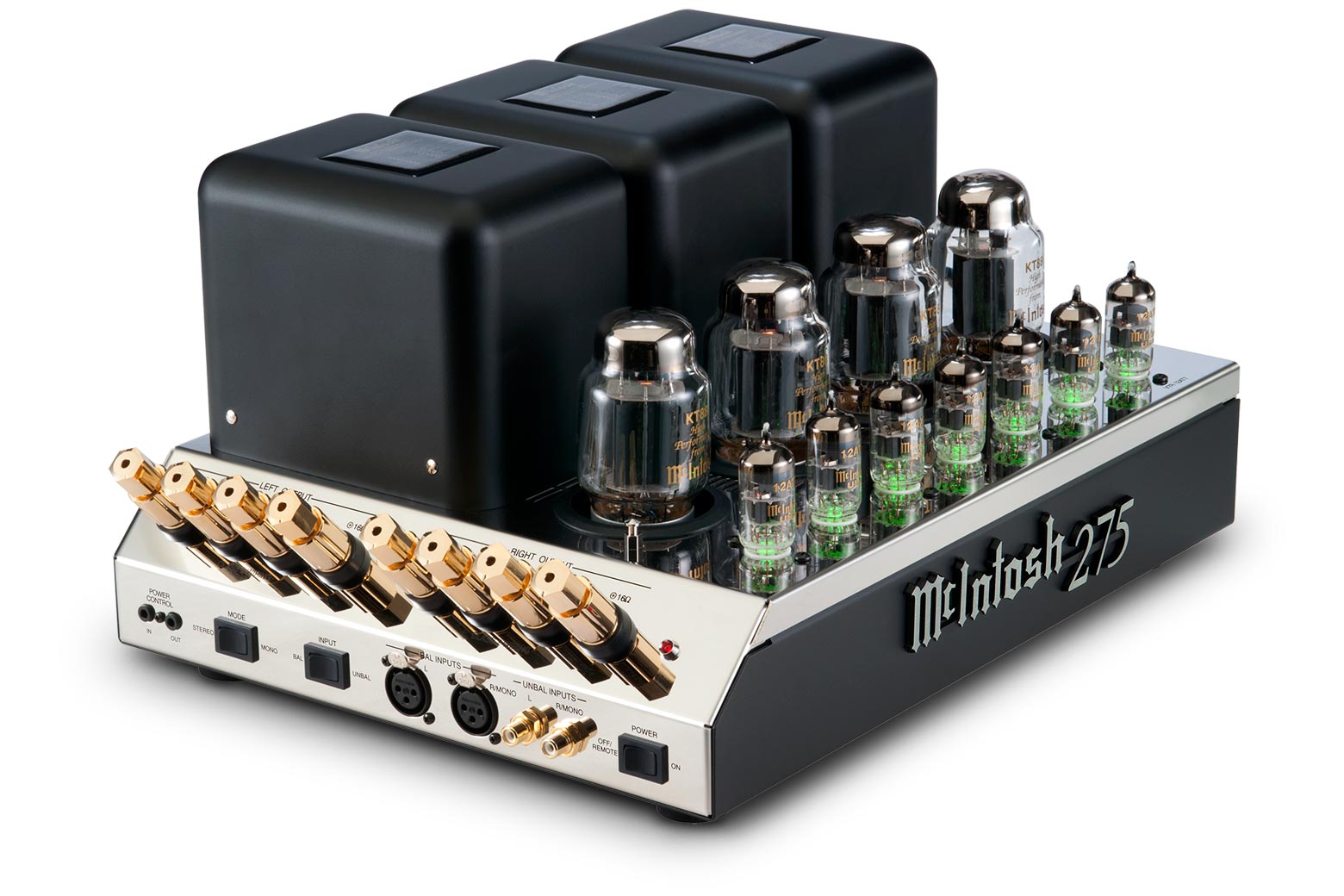
I wonder how much that gold is worth, another form of TE rape.
Zooming out on the schematic shows other interesting features...
The "ablist" joke...
Measuring times in units of conductance (a pet peeve of mine)...
The nuvistor at the bottom left is a tuned circuit frequency doubler, 50MHz on the gate, 100MHz on the anode...
The 200MHz and 500MHz filters.
For fun, I've also shown one of the two transistor divide-by-5 circuits. 1ms pulses on D260, 5ms pulses on Q275 emitter. Q273 merely buffers the output to drive external circuits. If you monitored the voltage on C263 with an analogue voltmeter, and you would have a digital display of the current count.
You do not have the required permissions to view the files attached to this post.


