Page 4 of 4
Re: TEK TM503 Project
Posted: Thu Oct 10, 2024 5:58 pm
by MED6753
The mystery of what's inside that part will be resolved once I cut it open with a dremel. The replacement parts should arrive tomorrow (Friday).
Re: TEK TM503 Project
Posted: Fri Oct 11, 2024 1:11 pm
by bd139
Something suspect going on there.
I would pull the divider network and test it externally before going anywhere near replacing it or opening it lest one ends up with two problems to solve

Re: TEK TM503 Project
Posted: Fri Oct 11, 2024 1:33 pm
by tggzzz
The tekwiki page has photos. One is
Re: TEK TM503 Project
Posted: Fri Oct 11, 2024 1:53 pm
by MED6753
bd139 wrote: ↑Fri Oct 11, 2024 1:11 pm
Something suspect going on there.
I would pull the divider network and test it externally before going anywhere near replacing it or opening it lest one ends up with two problems to solve
Go back and read. I did pull it before testing.
Re: TEK TM503 Project
Posted: Fri Oct 11, 2024 6:28 pm
by MED6753
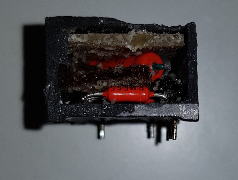
OK gang, I opened up the assembly and I found the problem. And my hunch was totally correct.
As proof, the unit on the bench and measuring the 9MEG resistor. NFG.

I opened it up with a dremel. That large resistor clearly says 9MEG/0.1%.

I checked directly across the resistor. Again, NFG.

This gooey crap was between the 9MEG resistor and the others below it.

I cut one lead of the 9MEG to isolate it and surprise, surprise....measures 9MEG. That gooey crap plus a foam pad on the cover has gone conductive over the years and was shunting the 9MEG resistor. My hunch was 100% correct.

I restored the 9MEG back into circuit and measures 9MEG as it should. Now I know why this assembly has a TekWiki page. They are ALL bad. I'm not going to re-install the cover and put it back into the DMM as is. The replacement tants will arrive today and once that's done I'll reassemble everything and test.

Re: TEK TM503 Project
Posted: Fri Oct 11, 2024 7:27 pm
by ch_scr
Good hunt! That plastic was likely part of the high voltage isolation though, (together with the outer shell).
If nothing conductive is close to it when assembled, it should be fine. (that should include a healthy gap between resistor bodys)
Now from the precision point, it could be argued this works better / more as a network when the resistors have their own little draft shielded house, thermally isolated from the environment and somewhat loosely thermally coupled together. But it probably won't make a difference here.
Re: TEK TM503 Project
Posted: Fri Oct 11, 2024 7:37 pm
by bd139
MED6753 wrote: ↑Fri Oct 11, 2024 1:53 pm
bd139 wrote: ↑Fri Oct 11, 2024 1:11 pm
Something suspect going on there.
I would pull the divider network and test it externally before going anywhere near replacing it or opening it lest one ends up with two problems to solve
Go back and read. I did pull it before testing.
You can’t expect me to actually read shit
Interesting finding though!
Re: TEK TM503 Project
Posted: Sat Oct 12, 2024 11:33 am
by nixiefreqq
did you by any chance stick your probes directly in the gooey crap just to see how conductive it is?
maybe you would need an hp 4329a or some such for this test? (always wanted one, but am still searching)
"The 4329A is a solid-state insulation resistance meter designed for easy, accurate and direct readings of very high resistance values typically found in synthetic resins, porcelain, insulating oils and similar materials."
Re: TEK TM503 Project
Posted: Sat Oct 12, 2024 1:15 pm
by MED6753
nixiefreqq wrote: ↑Sat Oct 12, 2024 11:33 am
did you by any chance stick your probes directly in the gooey crap just to see how conductive it is?
No I didn't because the stuff was falling apart and stuck to everything it came into contact.
Re: TEK TM503 Project
Posted: Sat Oct 12, 2024 10:44 pm
by Specmaster
MED6753 wrote: ↑Fri Oct 11, 2024 6:28 pm
OK gang, I opened up the assembly and I found the problem. And my hunch was totally correct.
As proof, the unit on the bench and measuring the 9MEG resistor. NFG.
I opened it up with a dremel. That large resistor clearly says 9MEG/0.1%.
I checked directly across the resistor. Again, NFG.
This gooey crap was between the 9MEG resistor and the others below it.
I cut one lead of the 9MEG to isolate it and surprise, surprise....measures 9MEG. That gooey crap plus a foam pad on the cover has gone conductive over the years and was shunting the 9MEG resistor. My hunch was 100% correct.
I restored the 9MEG back into circuit and measures 9MEG as it should. Now I know why this assembly has a TekWiki page. They are ALL bad. I'm not going to re-install the cover and put it back into the DMM as is. The replacement tants will arrive today and once that's done I'll reassemble everything and test.
Well sleuthed, Watson

Re: TEK TM503 Project
Posted: Sun Oct 13, 2024 8:04 pm
by MED6753
Bloody tants.

They all measured good but we all know that can change at the next power up.

It's
FIXED!!!! The contaminated network was the source of the inaccurate DCV. I'll bet almost all the DM501's on Ebay sold as not working suffer from the same issue. This one now tracks fine to the AD584-M reference after adjustment. I'm going to let it burn in for several hours then do a more in depth calibration. I'll post the results.

Re: TEK TM503 Project
Posted: Mon Oct 14, 2024 8:10 am
by MED6753
Specmaster wrote: ↑Sat Oct 12, 2024 10:44 pm
Well sleuthed, Watson
Elementary my dear Sherlock.

Re: TEK TM503 Project
Posted: Mon Oct 14, 2024 10:02 am
by tggzzz
MED6753 wrote: ↑Fri Oct 11, 2024 6:28 pm
OK gang, I opened up the assembly and I found the problem. And my hunch was totally correct.
...
This gooey crap was between the 9MEG resistor and the others below it.
...
I cut one lead of the 9MEG to isolate it and surprise, surprise....measures 9MEG. That gooey crap plus a foam pad on the cover has gone conductive over the years and was shunting the 9MEG resistor. My hunch was 100% correct.
Nice work. I suppose the only remaining question is what solvent, if any, did you use to remove the crap?
Re: TEK TM503 Project
Posted: Mon Oct 14, 2024 11:57 am
by MED6753
tggzzz wrote: ↑Mon Oct 14, 2024 10:02 am
MED6753 wrote: ↑Fri Oct 11, 2024 6:28 pm
OK gang, I opened up the assembly and I found the problem. And my hunch was totally correct.
...
This gooey crap was between the 9MEG resistor and the others below it.
...
I cut one lead of the 9MEG to isolate it and surprise, surprise....measures 9MEG. That gooey crap plus a foam pad on the cover has gone conductive over the years and was shunting the 9MEG resistor. My hunch was 100% correct.
Nice work. I suppose the only remaining question is what solvent, if any, did you use to remove the crap?
100% IPA and a soft brush.
Re: TEK TM503 Project
Posted: Tue Oct 15, 2024 7:20 pm
by MED6753
OK, let's get this DM501 calibrated and completed.
First up. As noted prior the Ohms was flaky. Due to a dirty range switch. Deoxit fixed that. And it did require a minor adjustment of the ohms calibration pot. Now in spec in all ranges but I still don't like that it doesn't have a 200 ohm range. That's a dumb oversight IMHO.

Next up. DCV. Checked with 190mV, 1.9V, 19V, and 190V. In spec on all ranges. Also it doesn't have 200mV range. Are you catching a pattern here?

I don't have an ACV reference other than 1.00V and it checked OK. Also can't verify the temperature functions since I don't have the proper probe.
So here it is completed and installed in the TM503.

Re: TEK TM503 Project
Posted: Tue Oct 15, 2024 8:51 pm
by bd139
Looking good

